3D Laser Scanning of Technological Complexes

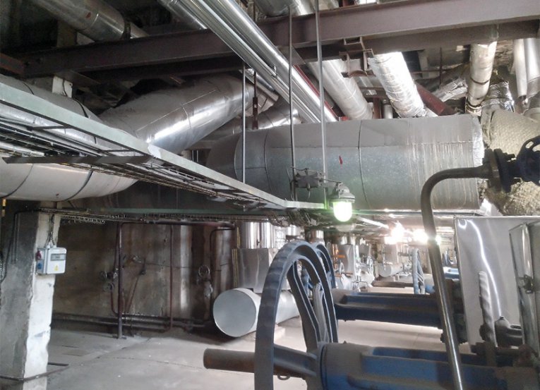
3D laser scanning is a very accurate, fast and safe contact-free method used for survey of real state of complicated technological complexes, such as industrial halls, assembly lines and equipment, complicated pipelines and other complex units. The target is to create virtual model of a real object with minimal loss of information about its dimensions and shape.
Use of Laser Scanning
- bases for changes of assembly lines for project architects in 3D
- passage studies
- bases for GIS of pipeline systems and their import to CAD software, such as Catia, Autodesk Inventor, etc.
- bases for construction documentation in 3D
Advantages of Laser Scanning
- complex survey of as-built
- high survey speed
- possibility to scan during operation
- high resolution (in millimeters)
- less expensive and faster realisation (everything is designed according to as-built)
3D Laser Scanning Principle
Laser scanning and consequent processing of measured data requires costly hardware and software equipment that ensures very quick, accurate and low-price data gathering and processing of large data volume.
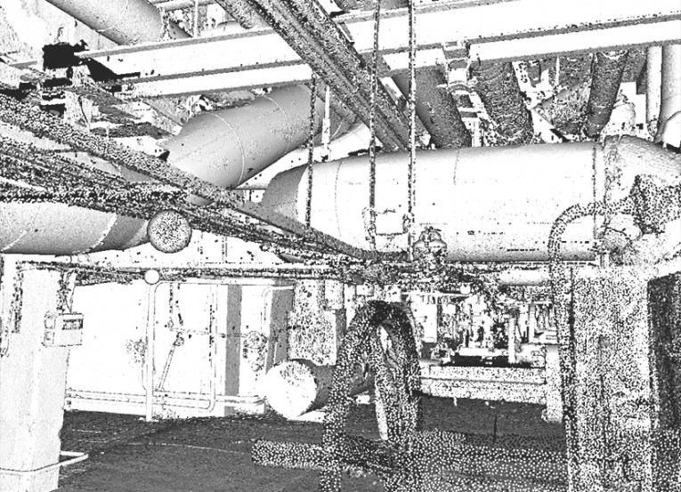
3D scanner uses a phase-shift or a pulse laser technology for length measurement and a space polar method in order to determinate coordinates directly in a 3D area. The density of points that describe surface of scanned objects is determined by the resolution in vertical and horizontal direction (usually 5 × 5 mm). So-called point cloud, a large set of points (up to hundreds of millions) defined by three-dimensional coordinates, is a primal output of laser scanning. The point cloud carries very accurate information about the shape and dimensions of measured objects.


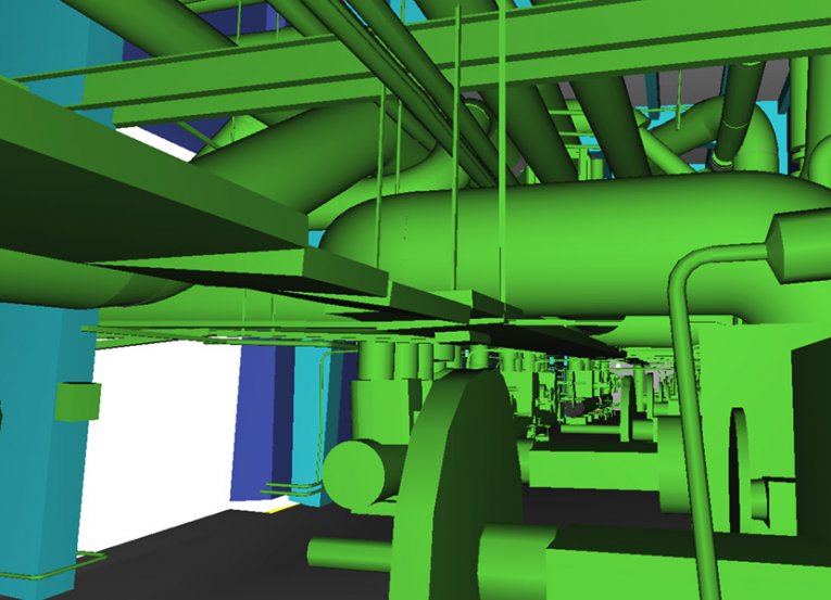
It is useful to transform the point cloud to CAD model for further data processing. Translation to CAD format is performed in specialized applications where scanned points are one-by-one substituted by standardized objects (pipe, H-beam, flange…) or by simple objects (block, lever, sphere…) that accurately describe more complicated objects. Formats that are regularly used in CAD applications such as STEP, WRL, 3Ds and others figure as output.
Laser Scanning – Order Process
- Order scope definition based on customer’s requirement – in ideal case from already existing documentation.
- Project results specification, in other words what is important for the customer – for example pipeline system in the object, load-bearing construction, building itself, assembly line, pipeline axes, etc. Scanning settings are adjusted according to required results.
- 3D scanning of the object itself – laser scanning of building using technology progresses in approximately 500 m³ per day.
- Registration of obtained point clouds, that means assembly of particular scanned point cloud into one coordinate system.
- Modeling of required objects into CAD format – we obtain 3D model of the as-built with 1‑cm accuracy.
Follow-up Steps (under customer’s responsibility)
- Designing activities during which new equipment is placed into the 3D model and connected to existing technology.
- Realisation according to the project – regarding accuracy of measurement, geodetic survey is processed quick and without complications.